In the after-treatment line of polyester staple fiber production, although the fiber strength after drawing is high, because of the large internal stress, the fiber shrinks under the heat action, and the stability is not good. In order to improve the fiber’s thermal stability, it is necessary to eliminate the residual stress due to drafting and promote crystallization by utilizing the annealer. The function of the annealer is to eliminate the internal stress of the fiber, improve fiber stability and its physical and mechanical properties. The annealer is particularly important in a polyester staple fiber production line.
Equipment problems and analysis
In the most recent four years, the polyester staple fiber market is flourishing. However, the annealer in polyester staple fiber production lines often suffers oil leakage in the roller shaft. This is a problematic situation, as the lubricating oil is key to the effective operation of the machinery. On the one hand, lubricating oil forms an oil film to reduce friction between rolling bodies; and on the other hand, it takes away a lot of heat generated by rolling friction. The oil leakage not only affects the site environment, but also sometimes splashes on the fiber, seriously affecting the fiber quality. And this is problematic because fiber quality requirements are increasingly strict, and once the oil is leaked, it seriously affects production capacity and consumes a lot of labor costs.
According to production and line running experience, the amount of lubricating oil required is 1.5 L/min for the front bearing, 1 L/min for the rear bearing, 0.5 L/min for the input shaft and the bridge shaft bearings, and 5 L/min for the gear engagement.
The first group of rollers for the annealer require the most oil flow. For seven sets of roller shafting, the total flow of bearings and gears used in the input shaft and the bridge shaft is 81 L/min, which is supplied by a 89 L/min gear oil pump.
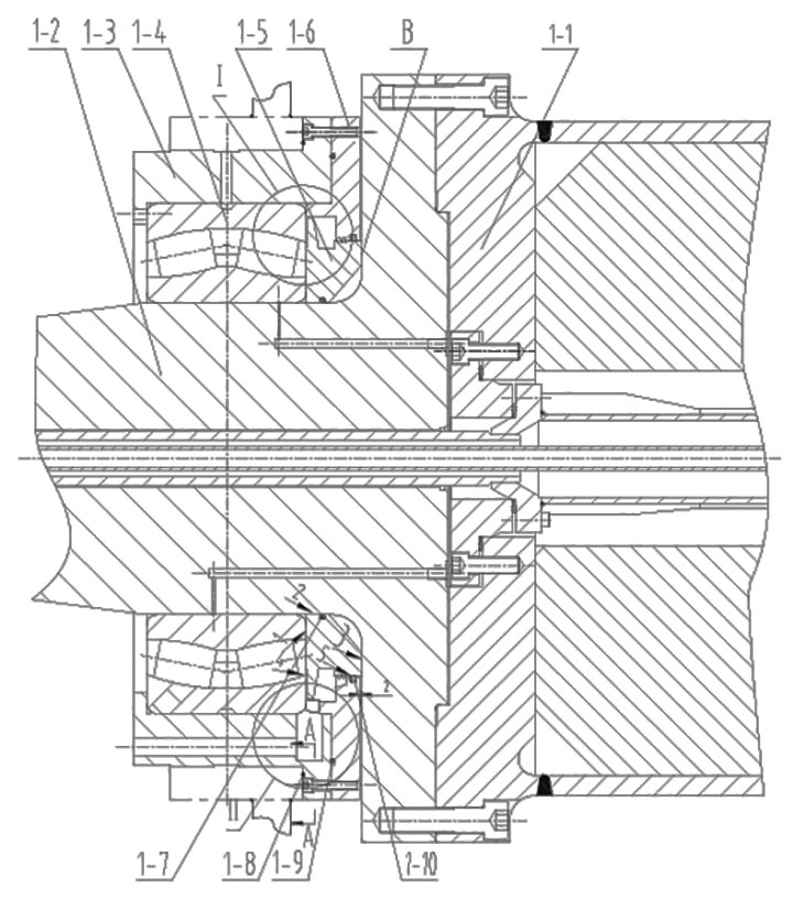
As can be seen from Figure 1, oil can be thrown out from the 2 mm gap between 1-6 oil return pans and 1-2 big shafts from the contact surface 1 between 1-4 bearing inner rings and 1-5 oil retaining rings, through the gap 2 between 1-5 oil retaining rings and 1-2 big shafts, to the big flange 3 of 1-2 big shafts. The other is that the oil return chamber is too small, 1-10 high water base disc seal failed, oil leaked from the 2 mm gap between 1-6 oil return pan and 1-2 large shaft in Figure 1, 4-5.

Optimization and improvement solutions
The roller shafting can be operated as follows: The 0.25 mm unilateral gap between 1-5 oil retaining rings and 1-2 large shafts is designed as interference fit, and the interference amount is increased from H7/P6 (-0.098 mm ~ -0.005 mm) to K7/P6 (-0.138 mm ~ -0.045 mm), so that the oil retaining ring and shaft are integrated to prevent small interference amount or process deviation.
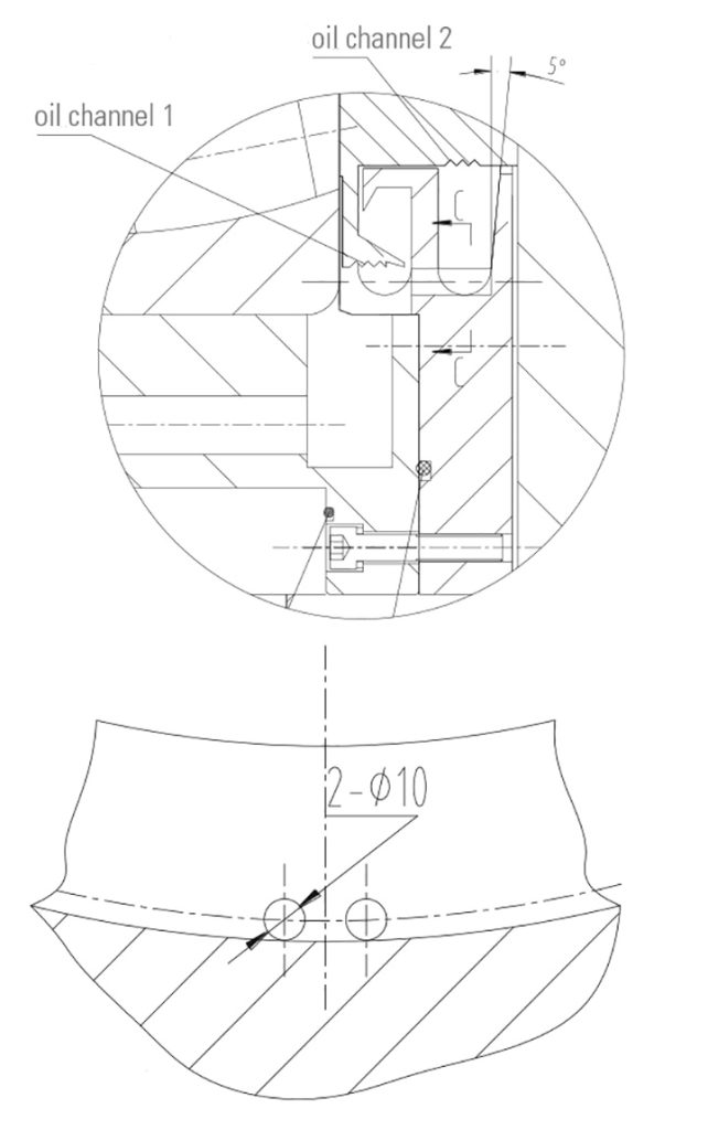
Scheme 2: in the 1-5 retaining ring outward-facing section, corresponding to the oil return plate cavity, three oil grooves are processed, as shown in the enlarged Figure 1. When the line is running, the oil can easily produce centrifugal force and flow into the oil return plate cavity, and the oil returns to the box body through the oil return hole in the cavity.
Scheme 3: Reduce the pressure in the oil channel; reduce the amount of oil. There are two ways to achieve this: A. Add a bypass before and after the oil pump, adjust the bypass valve body to make the oil pressure to the box at 0.2 mpa; the excess oil will flow back to the oil pump inlet; B. A pressure-relief bypass is added to the end of the oil pipe inside the box body.
Scheme 4: The roughness of the contact surface between 1-5 oil retaining ring and 1-10 high water-based coil is improved from Ra 1.6 to Ra 0.4, so that the sealing effect of static and static surface is better, and the damage of high water-based coil caused by rough contact surface is avoided, resulting in sealing failure and oil leakage.
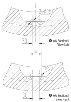
Bottom: AA Sectional view right
Scheme 5: As shown in enlarged Figure 1a, the length dimension L1 is designed from 3 mm to 1 mm, while the radial dimension H1 is reduced as much as possible. SKF, FAG and domestic bearings were checked, and the dimensions of the inner diameter of the outer ring of bearings are given, but the sizes are inconsistent, and the difference is not significant, while NSK does not give them.
According to the situation under consideration here, the roller shafting adopts imported bearings and each time the bidding is conducted, it is believed the minimum value can be selected according to the inner diameter given by SKF and FAG bearings, and then 5-10 mm can be reduced as the outer circle size of the inner ring shoulder of the 1-5 oil retaining ring and 1-4 bearing; i.e., the size H1 should be as small as possible under the consideration of both, and the recommended size is 5-8 mm. This can ensure that the bearing lubrication cooling oil can flow out and will not leave the oil in the oil chamber, due to reflux, resulting in oil outflow.
Scheme 6: In Figure 1b, the front bearing 1-4 moves 10 mm to the rear side, the width size L2 is 30 mm instead of 20 mm, and the capacity of oil return to the oil chamber of 1-3 bearing sleeve is increased.
Scheme 7: There are two 18 mm diameter oil return holes in the 1-3 bearing sleeve in the A-A sectional view, which are designed as A 22X52 mm waist shaped long round hole as shown in Figure 2, so that the oil returned to the oil chamber can quickly flow back to the box.
Scheme 8: Single point forced lubrication is used for bearings, screw holes are processed on the box panel, oil viewing device is installed, and the flow rate into the corresponding point can be adjusted and controlled.
Scheme 9: In the installation process, 1-5 oil retaining ring and 1-2 large shaft flange contact surface in Figure 1 must gel with the sealant. For the running equipment, in addition to Scheme 3, this operation can solve problems quickly and effectively. The other eight schemes need to be combined, such as shifting shaft, disassembling gears and bearings, replacing new parts or optimizing parts, which are suitable for equipment overhaul or new production equipment.
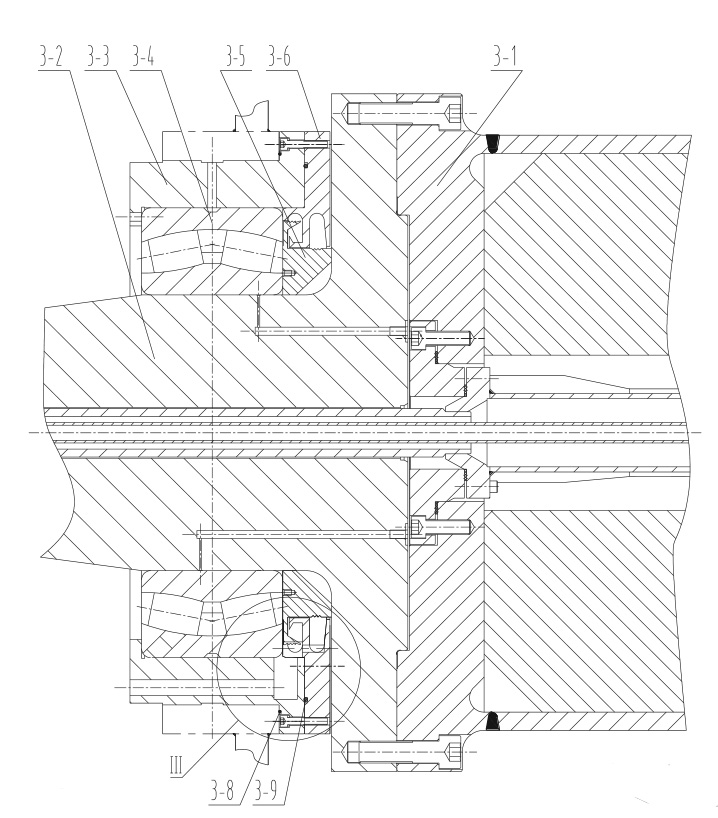
The new single machine can also adopt mechanical seals, as shown in Figure 3. The 1-5 oil retaining rings and 1-6 oil dumping discs in Figure 1 are changed, and the 1-7 O-rings and 1-10 high water base coils are cancelled. After optimization and improvement, the phenomenon of oil leakage in production operation is effectively avoided.